Ac Compressor Capacitor Wiring Diagram

Vt Commodore Ignition Wiring Diagram, Complete Wiring Diagrams For Holden Commodore VT, VX, VY, VZ, VE, VF, 5.36 MB, 03:54, 32,796, John Amahle, 2018-08-01T19:37:41.000000Z, 19, Vt Commodore Ignition Wiring Diagram, to-ja-to-ty-to-my-to-nasz-swiat.blogspot.com, 1272 x 1800, jpeg, bcm pcm 12j swiat nasz, 20, vt-commodore-ignition-wiring-diagram, Anime Arts
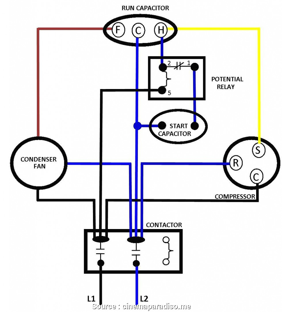
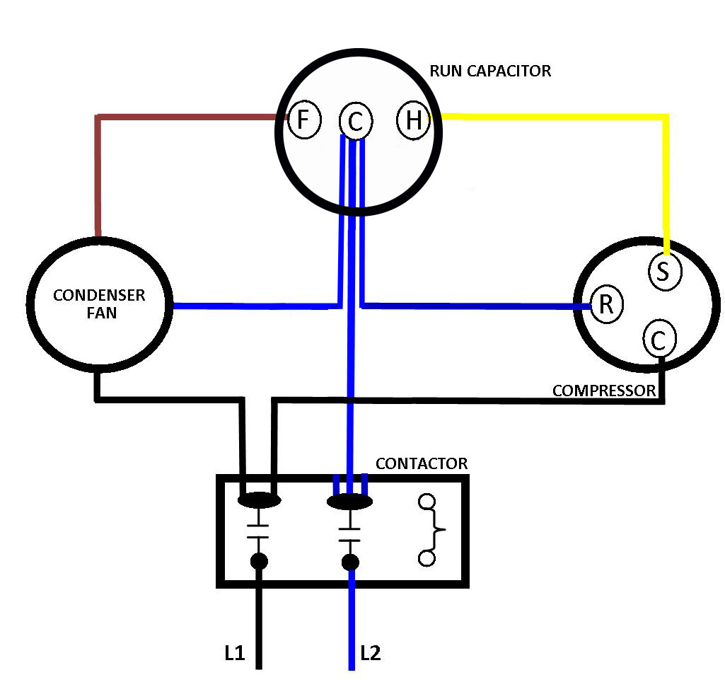
Capacitor unit air window conditioning replace hvac use draining professional experience call. Wiring diagram for ac compressor. Next, we’re wiring up our compressor. The compressor will have three wires coming out of it a wire coming from the common, the run, and the start windings.
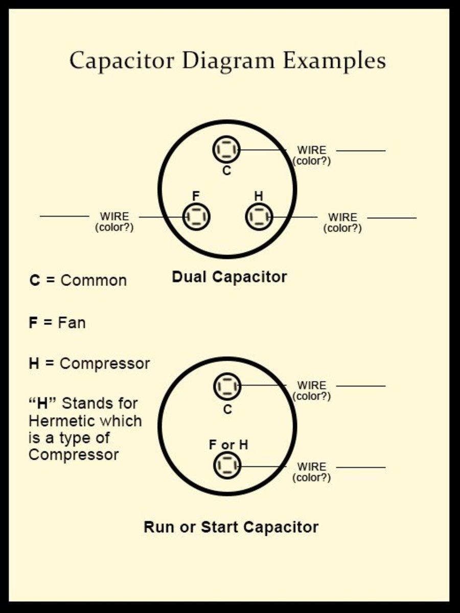
So if you have a dual run capacitor the start winding will always be. This video contains paid links that gives me a 6% commission if you click and buy any product on that website. This video contains paid links that gives me. The capacitor is wired between the power source and the compressor. The capacitor is needed to provide a constant voltage to the compressor, which helps it run more efficiently. A run capacitor provides a high voltage supply for a relay, starting circuitry, or fan relay. This video making for learning ac repairing work for new technician and for helpingabout this video this video in learn split ac window ac compressor wiring diagram. David talks about basic compressor wiring. In the event that your wiring has been taken off your terminals and there is no schematic diagram this is how a co.
Air Compressor Capacitor Wiring Diagram Before You Call A Ac Repair - Air Conditioner Wiring

Air Compressor Capacitor Wiring Diagram Before you call a AC repair man visit my blog for some

Compressor Start Capacitor Wiring Diagram Diagrams Schematics For Starting

Ac Outdoor Unit Capacitor Wiring Diagram - Ac Capacitor Cost And Replacement Ultimate Guide

How to Diagnose and Repair Your Air Conditioner (A/C) Capacitor - Dengarden

Capacitor For Compressor Wiring Diagram

Capacitor For Compressor Wiring Diagram

Wiring Diagram For Capacitor Start Motor | Refrigerator compressor, Refrigeration and air

Capacitor For Compressor Wiring Diagram

17+ Compressor Capacitor Wiring Diagram | Ac wiring, Electrical circuit diagram, Ac capacitor
