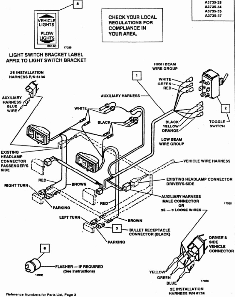
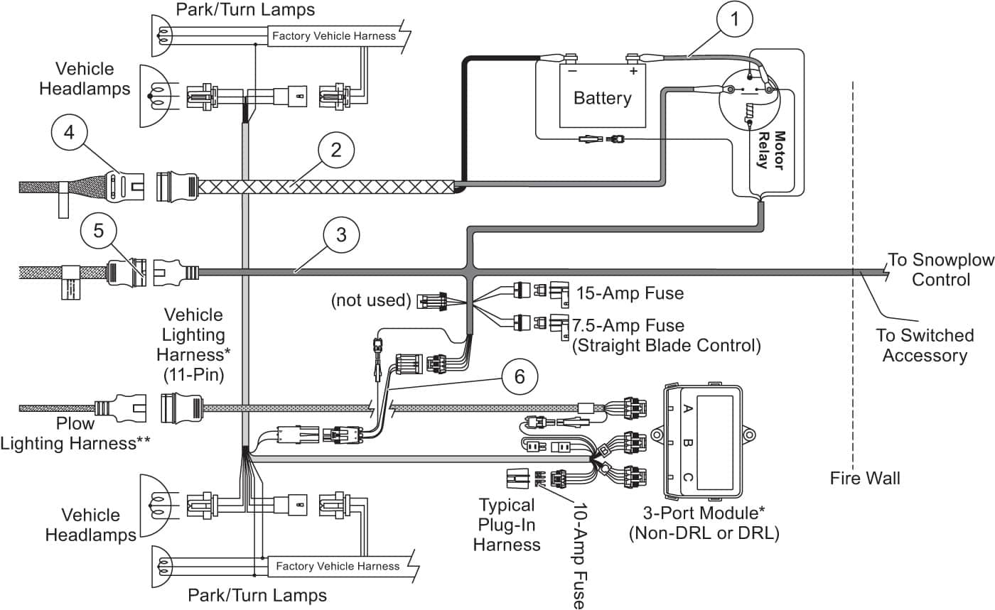
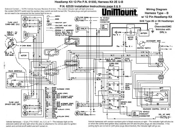
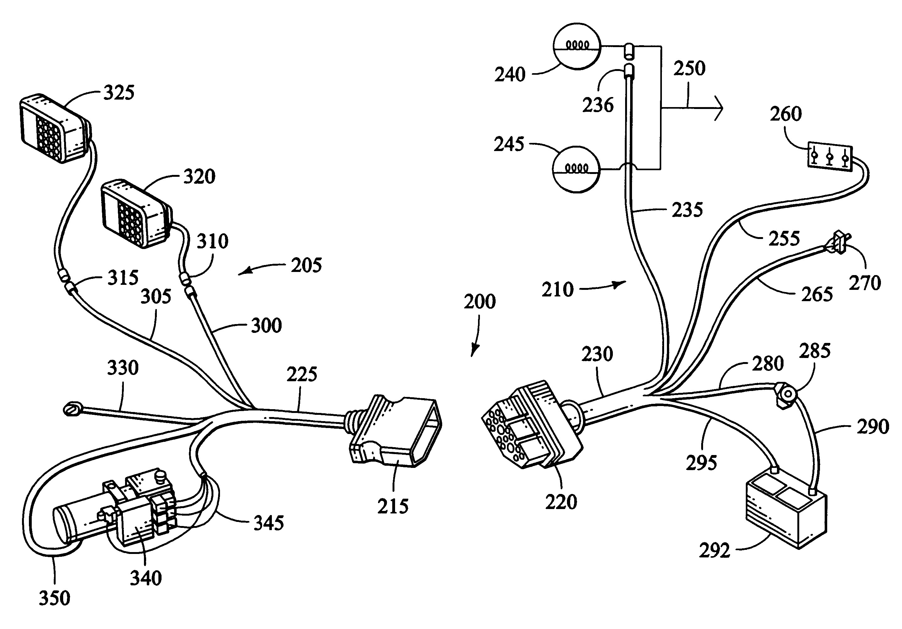
Boss V Plow Wiring Harness Diagram

Vt Commodore Ignition Wiring Diagram, Complete Wiring Diagrams For Holden Commodore VT, VX, VY, VZ, VE, VF, 5.36 MB, 03:54, 32,796, John Amahle, 2018-08-01T19:37:41.000000Z, 19, Vt Commodore Ignition Wiring Diagram, to-ja-to-ty-to-my-to-nasz-swiat.blogspot.com, 1272 x 1800, jpeg, bcm pcm 12j swiat nasz, 20, vt-commodore-ignition-wiring-diagram, Anime Arts
Boss v plow wiring diagram. Remove left blade half (5) and right blade half (4) from the crate. It shows the way the electrical wires are interconnected and. This is an oem wiring harness from boss located on the vehicle side of your plow wiring setup.
Secure wiring harness g10126 32. Secure wiring harness (61) to light bar (13) as shown above. Insert the unconnected ends of the plow wiring harness into the back of the coupler through the rubber grommet. Connect the plow side wiring harness to the hydraulic valve manifold as shown in figure 26. Hyd07044 with smarthitch2tm wiring. Boss v plow wiring diagram western plow wiring diagram best boss plow wiring diagram new. 8 27 2004 9 59 47 pm. Click on the image to enlarge and then save it to your computer by right clicking on the image. This is the complete truck side wiring kit for all boss v.
Boss V Plow Wiring Diagram | Free Wiring Diagram

Boss V Plow Wiring Diagram | Wiring Diagram

Boss V Plow Wiring Diagram | Wiring Diagram

[DIAGRAM] What Are Stereo Wiring Diagrams Used For Wiring Diagram FULL Version HD Quality Wiring
![Boss V Plow Wiring Harness Diagram [DIAGRAM] What Are Stereo Wiring Diagrams Used For Wiring Diagram FULL Version HD Quality Wiring](https://faceitsalon.com/wp-content/uploads/2018/07/the-boss-snow-plow-wiring-diagram-simple-wiring-diagram-for-boss-snow-plow-boss-plow-wiring-diagram-v-boss-v-plow-wire-harness-installation-boss-snow-plow-wiring-harness-18d.jpg)
Boss Snow Plow Wiring Harness

Boss Plow Wiring Schematic | Free Wiring Diagram

Boss Rt3 V Plow Wiring Diagram - SHERRODSTAMPS

Fuse Box And Wiring Diagram - Part 59

Boss V Plow Wiring Diagram - Wiring Site Resource
Boss V Plow Wiring Diagram - General Wiring Diagram
