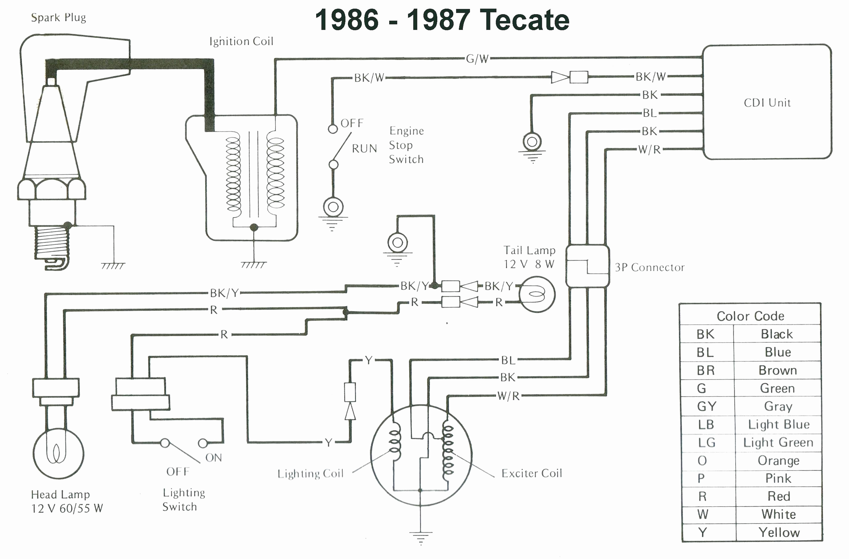
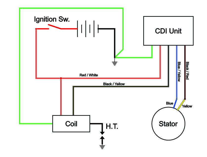
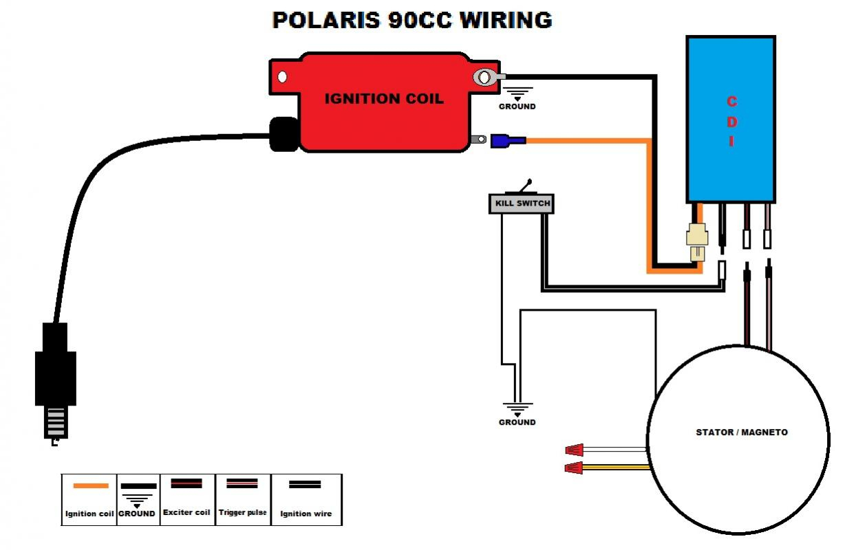
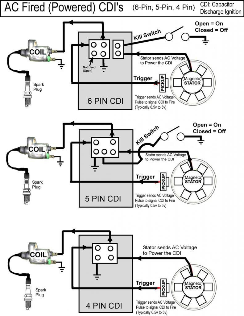
Cdi Ignition Wiring Diagram

Vt Commodore Ignition Wiring Diagram, Complete Wiring Diagrams For Holden Commodore VT, VX, VY, VZ, VE, VF, 5.36 MB, 03:54, 32,796, John Amahle, 2018-08-01T19:37:41.000000Z, 19, Vt Commodore Ignition Wiring Diagram, to-ja-to-ty-to-my-to-nasz-swiat.blogspot.com, 1272 x 1800, jpeg, bcm pcm 12j swiat nasz, 20, vt-commodore-ignition-wiring-diagram, Anime Arts
Tech support 1. 866. 423. 4832 customer service 1. 800. 467. 3371 www. cdielectronics. com 1 introduction and safety notice 2 general troubleshooting information. 2 troubleshooting guide better. Progress racing cdi wiring diagram 400hz means 400 x 60 = 24,000rpm, practically a 6 cyl. New racing cdi 5 pin wiring diagram.
New racing cdi tzr 50 wire. It is meant to help each of the typical user in building a proper system. The easiest way to determine if you have a cdi is to look at your oem wiring diagram and locate the kill switch. Once you've found it trace each wire leading away from it, there will likely just be two. One of them will go to the ignition module, the other wire will go to ground. The ground is the key, when the kill switch is activated it. Jun 26, 2017 cdi electronics supports the 2017 national skillsusa competition; Jun 28, 2016 cdi electronics announces new lower pricing for ficht emm repairs; White red and green from the stator go directly into the first 3 slots on the left of the cdi.
Cdi Ignition Wire - Today Wiring Diagram - 5 Pin Cdi Wiring Diagram | Cadician's Blog

110cc 5 Pin Cdi Wiring Diagram - Wiring Diagram

Cdi Wiring Diagram | Cadician's Blog

Cdi Capacitor Discharge Ignition Circuit Demo - Youtube inside Motorcycle Ignition Coil Wiring

Yamaha Cdi Ignition Wiring Diagram : DIAGRAM 110cc Atv Cdi Wiring Diagram FULL Version HD

Cdi Ignition Dc Cdi Wiring Diagram - Wiring Diagram

Cdi Ignition Wiring Diagram
60 Pro Comp Cdi Ignition Instructions - Wiring Diagram Harness

CX500 M-Unit & M-Button Wiring Diagram for CDI 1980 CX500A

Yamaha Cdi Ignition Wiring Diagram / DC-CDI schematic (updated) | Techy at day, Blogger at noon
